Clear electronics/RF guides, videos & downloads by Ian Poole | Resource hub for engineers & hobbyists | Shop: electronics-notes.com/store-…

Joined November 2016
10,199 Photos and videos
Have you ever needed to know what the codes on ceramic capacitors actually mean? From MLCCs to leaded discs, these components rely on different ceramic dielectrics to achieve their specific properties. Industry standards divide them into Classes based on performance, stability, and volumetric efficiency, making dielectric choice vital for your circuit design. 🧵 (1/5) #Electronics #MLCC #capacitors #PCB #Engineering #electronicsnotes #circuitdesign #HardwareEngineering #HardwareDesign #dielectric
1
2
9
406
Decoding Class 2 EIA tags is easy once you know how. Take the popular X7R: • The 1st letter 'X' means a low temp of -55°C. • The 2nd digit '7' indicates a high temp of 125°C. • The 3rd letter 'R' limits the max capacitance change to ±15%. Meanwhile, High-K types like Y5V and Z5U pack even more capacitance but experience steeper temperature variations. 🧵 (4/5)
1
57
The operational amplifier, or op-amp, is the fundamental building block of modern analogue electronics. Originally developed for mathematical operations in analog computers, these high-gain differential amplifiers are now ubiquitous. They are versatile, reliable, and provide the gain and impedance transformation needed to make complex circuit design straightforward, efficient, and highly effective. 🧵 (1/5) #opamp #operationalamplifiers #operationalamplifier #circuitdesign #hardwaredesign #hardwareengineering #amplifiers #electronicsnotes
1
2
34
1,202
Understanding the parameters is vital for success. From Slew Rate (how fast the output can change) and Gain-Bandwidth Product, to input bias currents and common-mode rejection—these specs dictate which op-amp is right for your design. Choosing the wrong device can lead to distortion, oscillation, or poor signal integrity, so knowing the data-sheet is truly an engineering essential. 🧵 (4/5)
1
1
172
Op-Amp Design: The Gain & Bandwidth Balance If you’ve ever had a situation where your high-gain amplifier response is "rolling off" sooner than expected, it’s likely you are encountering the Gain-Bandwidth Product (GBP) limits. In voltage feedback operational amplifier design, there is a fundamental trade-off: The more gain you want, the less bandwidth you get. Based on the insights from my Electronics-Notes website, here are three essential takeaways for your next analogue design: 1️⃣ The Open-Loop Reality: Most voltage-feedback op-amps (like the classic 741) have a surprisingly low open-loop breakpoint—sometimes as low as 6Hz! Beyond this point, the gain drops at a steady rate of -20dB/decade. 2️⃣ The GBP Constant: For standard voltage-feedback amplifiers, the Gain x Bandwidth remains constant. If you decrease your gain by a factor of 10, you gain a factor of 10 in bandwidth. It’s a literal balancing act. 3️⃣ Why Compensation Matters: Why is the bandwidth so limited? Internal frequency compensation is built into most ICs to ensure stability. Without it, your amplifier might turn into an oscillator! Pro-Tip: If your application requires high gain and high bandwidth simultaneously, you might need to move away from voltage-feedback op-amps and look into Current Feedback architectures, which don't follow the same linear GBP relationship. Are you hitting bandwidth bottlenecks in your current projects? Let’s discuss in the comments! Also for more details check out my website - link in the comments. #ElectronicsEngineering #CircuitDesign #AnalogDesign #OpAmps #HardwareDesign #EngineeringEducation #electronicsnotes
1
3
34
962
Check out the full breakdown on frequency response here: electronics-notes.com/articl…
1
1
375
ElectronicsNotes by Ian Poole reposted
Why You NEED An Emitter Follower In this video I explain what an emitter follower circuit is and why you need one in your circuits. These emitter follower amplifiers can be used in many circuits I've used them a huge number of times. In essence, an emitter follower is a common-collector configuration of a bipolar junction transistor or BJT. It's called an "emitter follower" because the emitter voltage closely follows the base voltage, even though there's a small voltage drop across the base-emitter junction. In its very simplest form, the circuit consists of a transistor and an emitter resistor. When a signal is applied to the base, it causes a corresponding current to flow through the collector and emitter. The emitter voltage closely tracks or follows the base voltage, there's just the base emitter junction difference which is about 0.6V for a silicon transistor. I look at the key characteristics of the emitter follower: 1. It has a high input resistance: This means the circuit draws very little current from the input signal source. It reduces the loading on the previous stage. This is typically beta, the transistor current gain times the overall emitter resistance including the load. 2. It has a low output resistance and this makes it suitable for driving lowish-impedance loads. 3. The voltage gain of an emitter follower is unity or 1 and 4. Finally the current gain - this is greater than 1, providing current amplification. I look at where emitter followers are used: a. Their chief use is as a buffer to reduce the load on a source. It could be an oscillator or anything where the loading may be an issue. b. In a similar vein they are used in impedance matching where it's necessary to match the impedance of a high-impedance source to a low-impedance load. The circuits can be directly coupled. Here the bias voltage for the device is taken from the previous stage. Alternatively they can be AC coupled, but here the bias network needs to be set up and the coupling capacitors selected to give the required frequency response. Watch my video now: youtu.be/fSki6td8L4c #emitterfollower #circuitdesign #HardwareDesign #electronicsnotes
3
3
27
1,312
What makes the Superheterodyne (or "Superhet") receiver the gold standard? Developed by Edwin Armstrong in 1918, this architecture solved the massive stability and selectivity problems of early radio. By converting incoming RF signals into a fixed "Intermediate Frequency" (IF), it created a stable, reliable way to tune stations. It’s the foundational technology that has underpinned almost every radio receiver—from broadcast AM/FM to modern high-end microwave communication systems—for over a century. 🧵 (1/5) #superhet #superheterodyne #radio #amateurradio #hamradio #hamr
2
7
46
1,990
Every Superhet relies on a few key building blocks working in harmony: * the RF Section, which selects the target signal; * the Local Oscillator, which provides the reference frequency; * the Mixer, which combines them to create the IF; * the IF Amplifier, where the majority of signal gain and selectivity actually happens; * the demodulator where the information is extracted from the signal; * typically there is a audio section that amplifies the signal to be presented to headphones of a loudspeaker. Understanding how these stages balance conversion gain and image rejection is essential for anyone looking to design or repair professional-grade radio hardware. 🧵 (4/5)
1
2
301
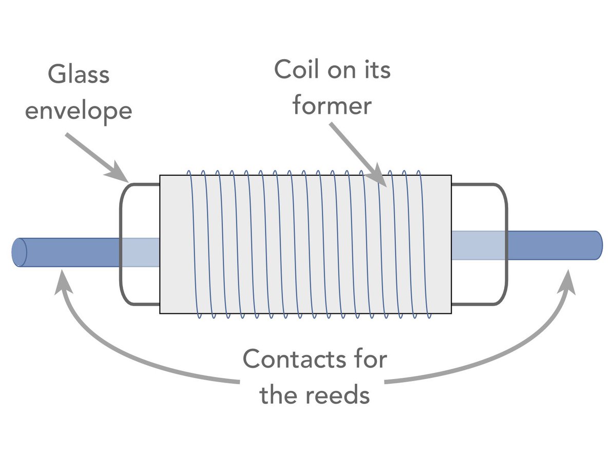
The Amazing Solution for Electronic Switching: The Reed Relay Ever wonder how electronic circuits achieve fast, reliable, and isolated switching without the bulk of traditional electromechanical relays? Meet the reed relay - a compact component that bridges the gap between traditional mechanical relays and solid-state alternatives. What is a Reed Relay? At its core, a reed relay consists of a reed switch - two overlapping nickel-iron blades hermetically sealed inside a glass envelope filled with inert gas (like nitrogen)—wrapped inside an electromagnetic actuating coil. When current passes through the coil, it creates a magnetic field that magnetizes the blades. They attract each other, snap shut, and close the circuit. Remove the current, the field drops, and the spring-loaded contacts snap back apart. Why Engineers Choose Reed Relays: * Speed: Because the gap between contacts is tiny (0.05 to 1 mm), they boast incredibly fast switching speeds—often between 0.5 to a few milliseconds. * Reliability & Longevity: Sealed inside glass, the contacts are entirely protected from moisture, oxidation, and contaminants. * Complete Isolation: They offer absolute physical isolation between the control circuit (coil) and the switched circuit. * Compact Size: They are small enough to fit into standard SIL or DIL integrated circuit packages, saving precious PCB real estate. Design precautions: While they are highly reliable, reed relays aren't always a "set-and-forget" component. When designing them into your circuits, remember: 1. Contact Bounce: The contacts collide with high energy, causing minor "bounces." If switching capacitive or inductive loads, this can cause arcing and reduce contact life. 2. Magnetic Interaction: Unscreened reed relays can experience magnetic coupling. If placed too close together on a PCB, their fields can oppose one another, requiring a higher coil voltage to close. Pro tip: Always look for reed relays with built-in ferrous metal screens to optimize efficiency and enable tight stacking! 3. Current Constraints: They are typically built for low-to-medium signal switching, not heavy-duty power applications. From test and measurement matrix switches to automated telecommunication exchanges, the reed relay remains an elegant, trusted solution for modern hardware engineering. More information- check the link in the comment. #ElectronicsEngineering #HardwareDesign #CircuitDesign #ElectronicComponents #ElectricalEngineering #electronicsnotes
2
4
49
2,130
👉 Want to dive deeper into the history, construction materials (like rhodium and ruthenium coatings), and circuit design considerations? Check out the full guide here: electronics-notes.com/articl…
449